
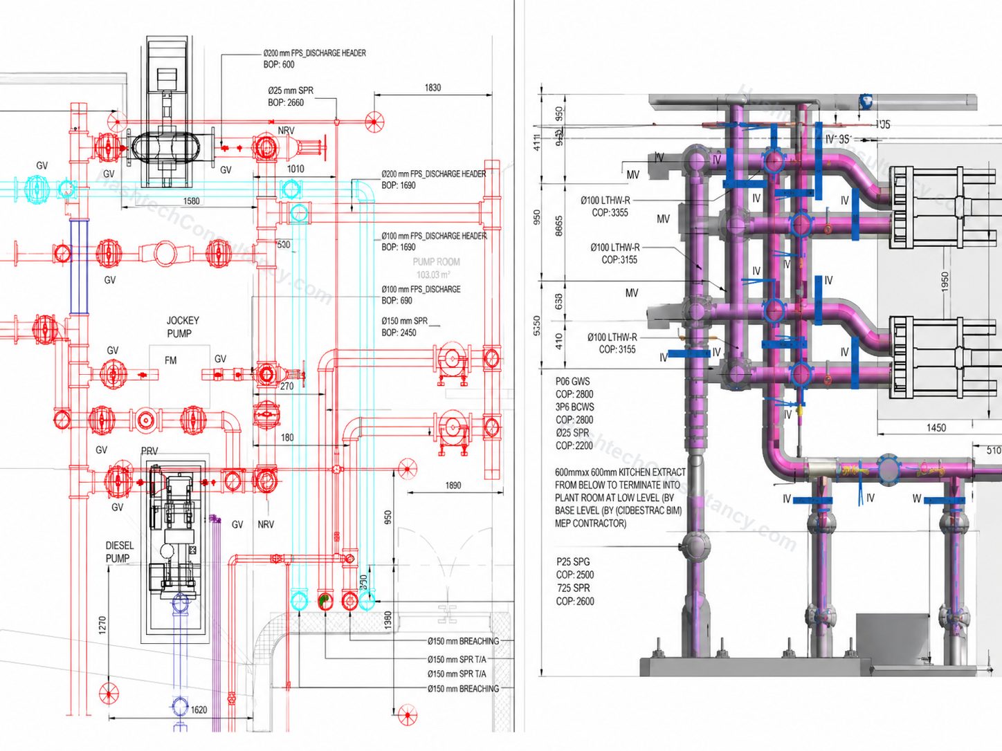
From Continuous Systems to Installable Units
Large building services systems can be difficult to fabricate, transport and install as one continuous network.
Spool and assembly drawings divide these systems into practical, identifiable sections that can be fabricated, checked, delivered and installed in a controlled sequence.
Our drawings are developed from coordinated BIM and fabrication information, with clear references to components, dimensions, connections, orientation and installation interfaces.
What We Develop
Pipe Spool Drawings
Break complex pipework networks into defined spool sections with detailed dimensions, fittings, connections and identification.
Ductwork Assemblies
Organise ductwork and associated fittings into manageable assemblies for fabrication, delivery and installation.
Equipment Assemblies
Document equipment and connected services as defined assemblies, making interfaces and connection requirements easier to understand.
Modular MEP Assemblies
Develop repeatable or prefabricated MEP assemblies that can be manufactured and installed as coordinated units.
Our Spool & Assembly Workflow
- 01
Review the Fabrication Model
Review the coordinated or fabrication-level BIM model to understand system geometry, components and project requirements.
- 02
Define Spools & Assemblies
Divide systems into practical fabrication and installation units based on size, access, transportation and installation requirements.
- 03
Assign Identification
Apply unique spool, assembly and component references to maintain traceability throughout the workflow.
- 04
Develop Detailed Drawings
Produce drawings showing dimensions, fittings, connections, orientation and other information required for fabrication and assembly.
- 05
QA/QC
Check spool geometry, dimensions, component relationships and connection points against the source model.
- 06
Issue for Fabrication & Installation
Prepare organised drawing packages for fabrication, assembly, delivery and site installation.
Every Component Has a Place
A useful spool drawing should allow the fabrication and installation team to understand the complete assembly without having to interpret the entire BIM model. Depending on the project, drawings can communicate:
Spool Identification
Unique references for fabrication and tracking.
Overall Dimensions
Key lengths, offsets and component dimensions.
Fittings & Components
Elbows, tees, reducers, valves, flanges and other components.
Connection Points
Clearly identified interfaces between spool sections and connected systems.
Orientation
Information required to understand how the assembly is positioned.
Installation References
Coordinates, levels or reference information where required.
Pipe Spooling
Fabricate in sections. Install with confidence.
Pipe spooling is particularly useful for complex mechanical, plumbing and fire protection systems. We develop spool drawings that organise pipework into practical fabrication sections while maintaining the relationship between:
- Pipe
- Fittings
- Valves
- Connections
- Equipment
This helps fabrication teams produce components in a controlled sequence while allowing installers to identify where each spool belongs on site.
Assembly Modelling & Drawings
Assemblies can be developed for systems that benefit from off-site preparation or modular installation. Typical examples include:
Pump Assemblies
Pumps, valves, fittings and associated pipework.
Valve Assemblies
Valves, flanges, fittings and connection arrangements.
Mechanical Modules
Pre-assembled pipework and equipment arrangements.
Repetitive MEP Modules
Standardised assemblies repeated across multiple floors or areas.
The exact assembly definition depends on the project's fabrication and installation methodology.
Fabrication to Installation
Spool and assembly drawings create a direct connection between what is fabricated and where it is installed. A typical workflow can be:
- Coordinated BIM Model
- Fabrication Model
- Spool / Assembly Definition
- Fabrication Drawing
- Workshop Production
- Site Installation
This provides a more traceable workflow for complex MEP fabrication projects.
Built for Prefabrication
Breaking systems into defined assemblies can support off-site fabrication and modular construction approaches. Potential benefits include:
Reduced Site Fabrication
Move suitable fabrication activities into a controlled workshop environment.
Improved Quality Control
Inspect components and assemblies before delivery to site.
Faster Installation
Install pre-defined assemblies rather than constructing every component individually on site.
Better Material Planning
Organise components and materials around specific fabrication packages.
Reduced Site Congestion
Limit the amount of fabrication activity required within constrained work areas.
Complex Areas Made Manageable
Plant Rooms
Complex pipework, equipment and valve arrangements.
Mechanical Rooms
Dense systems requiring detailed fabrication and installation planning.
Risers
Vertical pipework and services divided into manageable sections.
Service Corridors
Long, repetitive systems suitable for prefabricated sections.
Repetitive Floors
Standardised assemblies that can be fabricated and installed across multiple levels.
Typical Deliverables
Pipe Spool Drawings
Detailed documentation for individual pipework spools.
Assembly Drawings
Detailed representation of fabricated or pre-assembled components.
Spool Isometrics
Isometric views showing spool geometry, components and connections where required.
Assembly Details
Detailed views of equipment and component assemblies.
Spool Registers
Structured lists of spool references and associated information.
Material Information
Component and material schedules where required.
Installation References
Information linking fabricated units to their intended location.
Spool Identification & Tracking
Large fabrication projects can contain hundreds or thousands of individual spools and assemblies. A structured identification system can help track each unit through:
- Model
- Drawing
- Fabrication
- Inspection
- Delivery
- Installation
Spool references can be organised according to the project's preferred system, floor, zone, area or fabrication sequence.
Designed for Real-World Assembly
The objective is not simply to divide a model into smaller pieces. Each spool or assembly should be practical to fabricate, transport, handle and install within the project's actual constraints. Where project information allows, we consider:
- Access
- Handling
- Transportation
- Connection points
- Installation sequence
- Available working space
- Equipment interfaces
Spool & Assembly Drawing Services
Hashtech provides spool and assembly drawing services for MEP contractors, mechanical contractors, fabricators and construction teams working on complex building services projects. We develop detailed pipe spool drawings, spool isometrics, ductwork assemblies and MEP assembly drawings from coordinated BIM and fabrication models.
These deliverables support prefabrication, off-site assembly, material planning, fabrication, delivery and installation while maintaining a connection between the BIM model and physical construction.
Frequently asked questions
What are spool drawings?
Spool drawings divide a larger piping or building services system into individual fabrication sections, showing the components, dimensions and connections required to manufacture each section.
What is an assembly drawing?
An assembly drawing shows how multiple components come together to form a larger fabricated or pre-assembled unit.
What is the difference between a fabrication drawing and a spool drawing?
A fabrication drawing can document individual components or systems for manufacturing. A spool drawing specifically breaks a continuous system, typically pipework, into defined fabrication and installation sections.
Can you create pipe spool drawings?
Yes. We can develop detailed pipe spool drawings and spool isometrics for mechanical, plumbing and fire protection systems within the agreed scope.
Can you create spool drawings from Revit?
Yes. Coordinated Revit or fabrication models can be used as the source for developing spool and assembly documentation.
Can you provide spool registers?
Yes. Spool registers can be developed to track spool references and associated information where required.
Can spool drawings support prefabrication?
Yes. Spool documentation is commonly used to organise components into manageable units for workshop fabrication and subsequent site installation.
Complex systems. Clear assemblies.
Break your MEP systems into fabrication and installation packages built for the real world.
We’ll reply within one working day with questions, or with a scope and fee.