
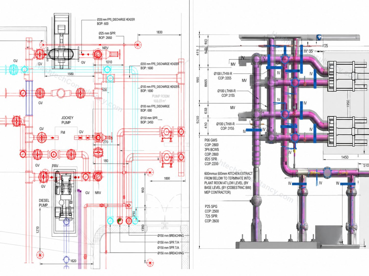
From Fabrication to Installation
A component can be correctly fabricated and still be difficult to install without clear site information.
Our installation drawing services provide construction teams with practical documentation showing where systems are installed, how they connect and what spatial requirements need to be maintained.
Using coordinated BIM and fabrication information, we develop drawings that help site teams work from a clear and consistent digital source.
What We Show
System Layouts
Show the location, routing and arrangement of building systems within the architectural and structural environment.
Levels & Dimensions
Provide accurate elevations, offsets, dimensions and reference points required for positioning components on site.
Connections & Interfaces
Clearly document how systems connect to equipment, structures, other services and adjacent installations.
Installation Details
Provide enlarged views and detailed information for areas where standard plans are not sufficient to communicate the installation requirement.
Our Installation Drawing Workflow
- 01
Review Coordinated Information
Review BIM models, fabrication drawings, shop drawings and project requirements to establish the approved installation information.
- 02
Identify Installation Requirements
Assess routes, levels, access, connections, interfaces and other information required by the installation team.
- 03
Develop Site Drawings
Create clear installation drawings showing the information required to position and install the systems.
- 04
Add Installation Detail
Include dimensions, elevations, references, sections, tags and enlarged details where required.
- 05
QA/QC
Check drawing information against the coordinated model and relevant fabrication documentation.
- 06
Issue for Installation
Prepare the final drawing package according to the project's drawing standards, numbering and issue requirements.
Designed for the Site Team
Installation drawings should answer practical questions quickly:
- Where does it go?
- What level should it be installed at?
- How does it connect?
- What does it connect to?
- What clearance is required?
- How does it relate to adjacent systems?
Our drawings are structured around these practical requirements, helping reduce interpretation during installation.
Installation Documentation for MEP Systems
Mechanical
Ductwork, pipework, HVAC equipment, plant and associated mechanical systems.
Electrical
Cable trays, containment, conduits, equipment and distribution systems.
Plumbing
Water supply, drainage, sanitary pipework, fixtures and associated systems.
Fire Protection
Sprinkler pipework, hydrants, hose reels, dry risers and associated equipment.
Installation Drawings for Complex Areas
Detailed installation information becomes particularly important where multiple systems share limited space.
Plant Rooms
Show equipment locations, service connections, elevations and installation relationships.
Risers
Communicate vertical service routes, levels, connections and interfaces.
Ceiling Voids
Provide clear information for installing dense MEP services within restricted spaces.
Service Corridors
Document service routes and installation relationships across congested areas.
Equipment Zones
Show equipment positioning, connections, access and surrounding installation requirements.
Model-Based Installation Documentation
Keep the drawings connected to the model.
Where installation drawings are developed from coordinated BIM models, the documentation can maintain consistency with the project's digital information.
- Coordinated BIM Model
- Fabrication Information
- Installation Drawings
- Site Installation
This approach helps reduce discrepancies between the digital model, detailed documentation and physical installation.
Installation Detail Where It Matters
Not every part of a project requires the same level of drawing detail. We can provide additional information for:
- Equipment connections
- Pipe and duct interfaces
- Service penetrations
- Levels and offsets
- Supports and access zones
- Complex routing
- Installation sequencing
- Existing-to-new connections
Typical Deliverables
Installation Plans
Detailed layouts showing system locations and routing.
Installation Sections
Vertical information showing levels, elevations and spatial relationships.
Enlarged Installation Details
Detailed views of complex installation conditions.
Equipment Installation Drawings
Equipment positioning, connections and associated service information.
MEP Installation Drawings
Detailed documentation for mechanical, electrical, plumbing and fire protection systems.
Installation Packages
Organised drawing sets structured by area, system, floor or installation sequence.
Installation Packages by Area
For larger projects, installation drawings can be organised into practical site packages.
By Floor
Level 01, Level 02, Level 03 and onward.
By Area
Plant room, riser, zone or corridor.
By System
Mechanical, plumbing, electrical and fire protection.
By Installation Sequence
First fix, second fix, equipment and final connections.
This allows site teams to access the information relevant to the work being carried out.
Built for Site Execution
The purpose of an installation drawing is simple: give the installer the right information at the right level of detail.
Our documentation focuses on clear graphical information, accurate dimensions and practical references so that complex BIM information can be translated into something the site team can use.
- Design
- Coordination
- Fabrication
- Installation
Installation Drawing Services for Construction
Hashtech provides installation drawing services for contractors, MEP contractors, fabricators and construction teams requiring clear documentation for site installation. We develop detailed MEP installation drawings from coordinated BIM models, fabrication information and approved project documentation.
Our drawings help site teams understand system locations, routing, elevations, interfaces and installation requirements before and during construction.
Frequently asked questions
What are installation drawings?
Installation drawings provide the practical information required to position, connect and install building systems and components on site.
What is the difference between shop drawings and installation drawings?
Shop drawings communicate detailed construction requirements. Installation drawings focus specifically on how and where the work is positioned and installed on site.
Can you create MEP installation drawings?
Yes. We can develop installation drawings for mechanical, electrical, plumbing and fire protection systems within the agreed project scope.
Can installation drawings be developed from BIM models?
Yes. Coordinated BIM models provide an effective source for developing accurate installation plans, sections, details and views.
Can you show installation levels and dimensions?
Yes. Drawings can include elevations, offsets, dimensions, reference points and other positioning information required by the project.
Can installation drawings be organised by area?
Yes. Drawing packages can be structured by floor, zone, plant room, riser, system or installation sequence.
Do you provide installation drawings for fabricated components?
Yes. Fabrication information can be incorporated into installation documentation where the project workflow requires it.
Need clearer information for site installation?
Turn coordinated digital information into drawings your installation team can work from.
We’ll reply within one working day with questions, or with a scope and fee.